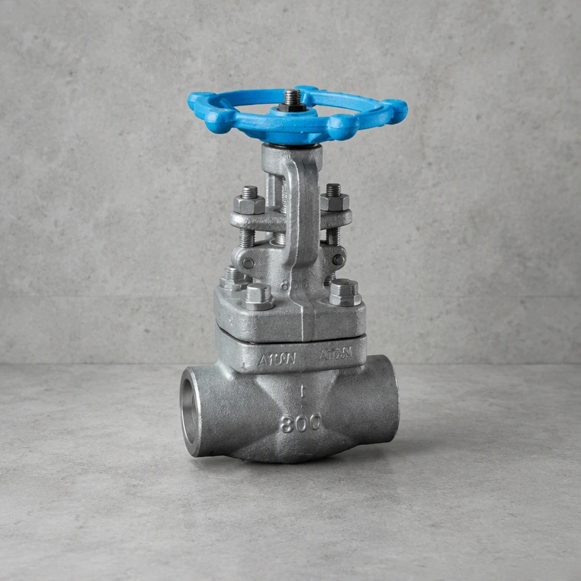
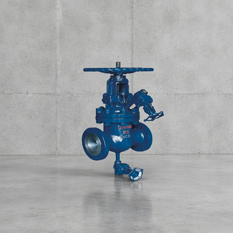
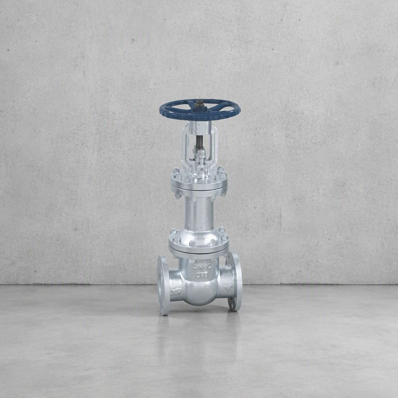
Q1. What is a flanged gate valve used for, and where is it used?
A1. A flanged gate valve is the general-purpose isolation valve for industrial piping. Flanged ends make it easy to install and to remove for maintenance, which is why it is the default choice wherever the line does not have to be welded.
Q2. What design variants are available, and how do I tell them apart?
A2. The main variants are solid wedge, flexible wedge and split wedge. A solid wedge is the simplest and suits clean, steady service; a flexible wedge absorbs the distortion that a body sees during thermal cycling and is preferred where temperature changes; a split wedge lets the two discs align independently, which suits high-temperature lines and valves that have to sit closed for long periods. The stem arrangement also differs: rising stem (outside screw and yoke) shows the position visually, non-rising stem saves headroom.
Q3. Which standards does this valve follow?
A3. Valves in this range are designed and manufactured in accordance with recognised industry standards rather than to a single in-house specification. The pressure and temperature framework normally follows ASME B16.34; ASME B16.10 covers face-to-face dimensions and ASME B16.5 the flange drilling; API 600 is the usual design reference for steel gate valves in the larger sizes, and API 6D where the valve is intended for pipeline service. Pressure testing follows API 598. Standards are applied as the design basis — the certificate of conformity issued with a delivery states which standard and which revision each item was built and tested to, so the drawing should be read together with that certificate.
Q4. How is the valve pressure tested before delivery?
A4. Testing is to API 598. The shell test is at 1.5 times the 38 °C rating and the seat test at 1.1 times, with the acceptance judged against ISO 5208 leakage rates. Two practical points are worth fixing before the order is placed: whether the seat test is carried out on both directions or only on the specified flow direction, and whether a test certificate with the actual recorded figures is required or a simple pass statement will do. On isolation valves for gas and for hazardous media the test figures are normally asked for and filed with the maintenance record.
Q5. What are the common failure modes, and how are they avoided?
A5. Four things cause most of the trouble. Scoring of the seating faces from trapped particles. Gland leakage from packing that has hardened or from a scratched stem. Corrosion of the stem and the bonnet bolting where water sits. And seizure of the disc after long periods without operation. None of these require a different valve — they require handling and a maintenance habit: keep the pipework clean before commissioning, operate the valve at least annually through its full travel, do not leave it part open, and inspect the packing and stem whenever the line is down.
Q6. How do I select the right one for my line?
A6. Match the flange standard and drilling to the existing pipe, then check the face-to-face dimension against the space available. Pressure class should be taken at the design temperature, not at ambient, because the allowable pressure falls as temperature rises.
Q7. How do I order, and what information is needed for a quotation?
A7. Ordering starts from the line list: tag number, size, class, medium, temperature, connection and operating method. Send that and we will confirm material and seat selection against the medium, flag anything that is likely to cause trouble on site, and quote accordingly. Special sizes, operators and materials are produced to order.