Q1. What is a high pressure check valve used for, and where is it used?
A1. A check valve prevents reverse flow and does nothing else — it is not an isolating valve and cannot be used to shut a line down. It is fitted wherever backflow would damage equipment, contaminate a line or drain a header: at the discharge of every pump, on compressor and blower outlets, on the suction of a pump fed from a pressurised source, downstream of a meter, at the outlet of a boiler feed line, and on any branch that must not drain back. It works automatically, with no operator and no external signal, so it has to be chosen so that it neither chatters at low flow nor slams when the flow reverses. Because it is a passive item with no adjustment once it is in the line, its closing behaviour is what decides whether it protects the line or damages it. At elevated temperature it is used on steam headers, superheater and reheater lines and on high-pressure process lines, where the rating has to be read at the working temperature rather than at the cold one.
Q2. What design variants are available, and how do I tell them apart?
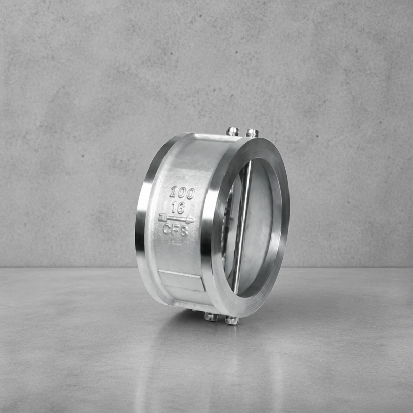
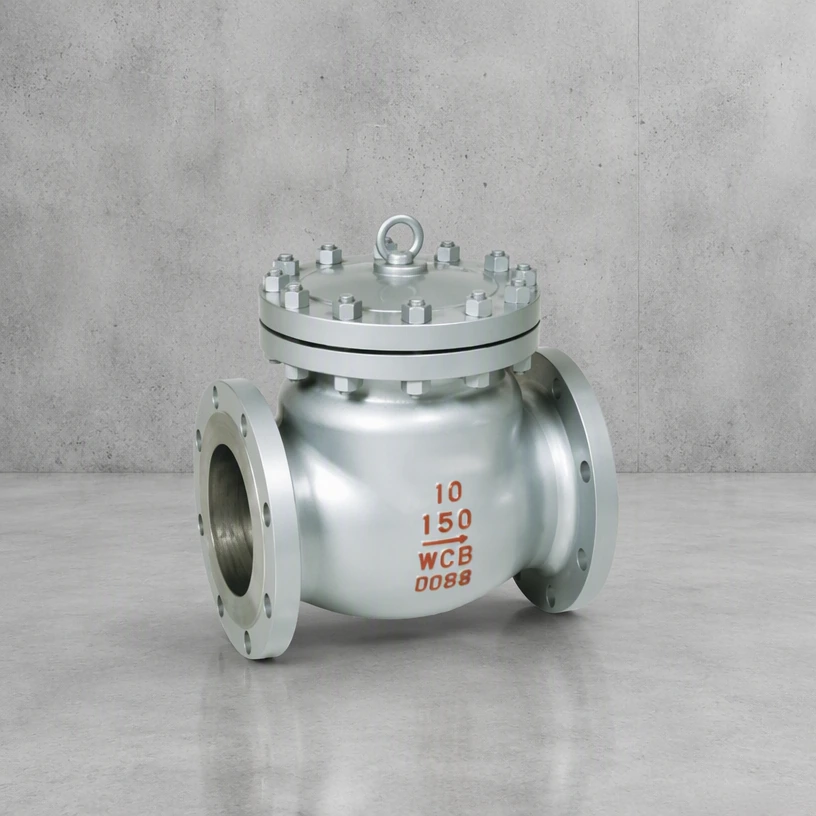
A2. The type is chosen from how much space is available and how fast the flow reverses. A swing check has a hinged disc and is the most common on water and steam mains, but it needs a long installation length and its disc can slam. A dual-plate (wafer) check puts two spring-loaded half discs in a short body, which suits tight spaces and reduces slam. A lift check guides the disc vertically and is used on high-pressure small-bore lines and where the flow is always in one direction. A tilting-disc check is the answer on large compressor and pump discharges, because the disc closes before the flow has fully reversed. Nozzle or axial checks use a spring-loaded ring around the axis and are chosen where the response has to be very fast.
Q3. Which materials are used as the temperature rises, and what sets the limit?
A3. Carbon steel such as WCB covers steam and hot oil up to roughly 425 °C. Above that the material steps up to chromium-molybdenum steel — 1.25Cr and 2.25Cr grades are the usual answer — because carbon steel starts to lose strength and is prone to graphitisation. Beyond roughly 540 °C the specification moves again, to 9Cr or austenitic grades, and selection is then made on creep behaviour rather than on tensile strength. The limiting component is almost never the body alone: bolting, gasket, packing and seat facing each have their own upper temperature, and the lowest of them governs the valve. Where the temperature cycles, fatigue life matters as much as the peak figure.
Q4. Which standards is this valve designed and tested to?
A4. These valves are built to published standards rather than to a catalogue number. The pressure and temperature framework normally follows ASME B16.34; ASME B16.10 covers face-to-face dimensions and ASME B16.5 the flange drilling. The design reference follows the type: API 600 for bolted-bonnet steel gate, globe and check valves in the larger sizes, API 602 for the compact forged versions, API 608 for ball valves, API 609 for butterfly valves, and API 6D where the valve is intended for pipeline service. Pressure testing follows API 598. The certificate of conformity issued with a delivery states which standard and which revision each item was built and tested to, so the drawing should be read together with that certificate.
Q5. How is the valve pressure tested before delivery?
A5. Two practical points are worth fixing before the order is placed: whether the seat test is carried out in both directions or only in the specified flow direction, and whether a test certificate with the recorded figures is required or a simple pass statement will do. On isolation valves for gas and hazardous media the recorded figures are normally asked for and filed with the maintenance record, because they are the baseline against which later leakage is judged.
Q6. How do I select the right one for my line?
A6. Work through the operating envelope rather than the normal condition. The normal condition gives the size; the maximum and minimum give the material and the seat. The extremes that matter are the highest temperature, the highest differential the valve will be asked to close against, and the most corrosive or most abrasive the medium will ever be — including during cleaning and start-up, when the fluid is often not what the design assumed. A valve sized on the normal condition alone will be the one that fails first.
Q7. How do I order, and what information is needed for a quotation?
A7. Give us the service conditions rather than only a model number: size, pressure rating, medium, temperature and connection. Where a standard applies, name it and the revision. Custom work is normal in this range — end connections, operator type, trim material and surface treatment are all specified per order.